Friday, 30 April 2010
Experience
As obviously, the buggy could not run on the magnetic strip but while working on this project, we learnt about robots and had practical experience of circuits, installation of motors, assembling different parts, soldering parts together. So, basically it was quite fun to work on this project. I wish, we could have given little bit more time, so that we could program it and make it alive.
Test Day
After the building, circuiting of the buggy was completed; it was the time to program our buggy. Since Xavier our team mate was very good at that, he took the responsibility to program it. Unfortunately in the last week we found out that he decided to drop out the university for some reasons. And then the test day came, we managed to program it but instead of moving forward, it was moving backward with one wheel not rotating because of the insufficient torque produced by the motor. So, we did not give it a try on the platform.

Monday, 26 April 2010
Picaxe 18X

The Picaxe 18X microcontroller is a digital device. It reads digital inputs that is binary numbers(0,1) where 0 means low and 1 means high. When the voltage is less than 3V, the input signal is been read as low(0) and when the voltage is greater than 3V, the input signal is read as high(1). This microcontroller also has pins that can be used as analogue inputs. This implies that we can read an analogue signal by changing each of the 8 bits of a byte as binary numbers. And this would be in the form of binary numbers. As we know that the byte variables range from 0 to 255, therefore the code has to be on this base. The input values from analogue to digital pins is stored in byte variables.
The Final Push
For the final circuit we needed to include 3 things: the motors, the reed switches and the picaxe.
We made the circuit on a breadboard for easy of construction and modification in the event of a mistake being made.
Bellow is the partially constucted circuit. The reed switches are simply plugged into the board as opposed to being on extended wires. This was purely so we could see their position clearly whilst we were still configuring the layout off the breadboard.
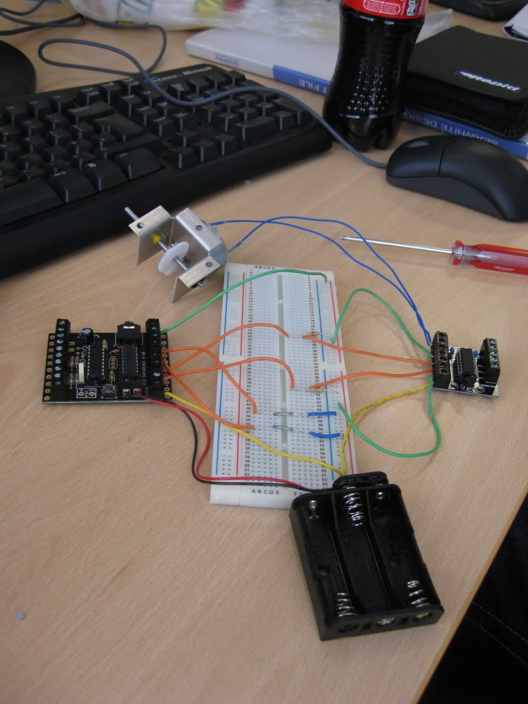
The final circuit has both reed switches on elongated wires in order for the sensors to be postioned on the chassis closer to the ground and therefore closer to the magnetic strip.

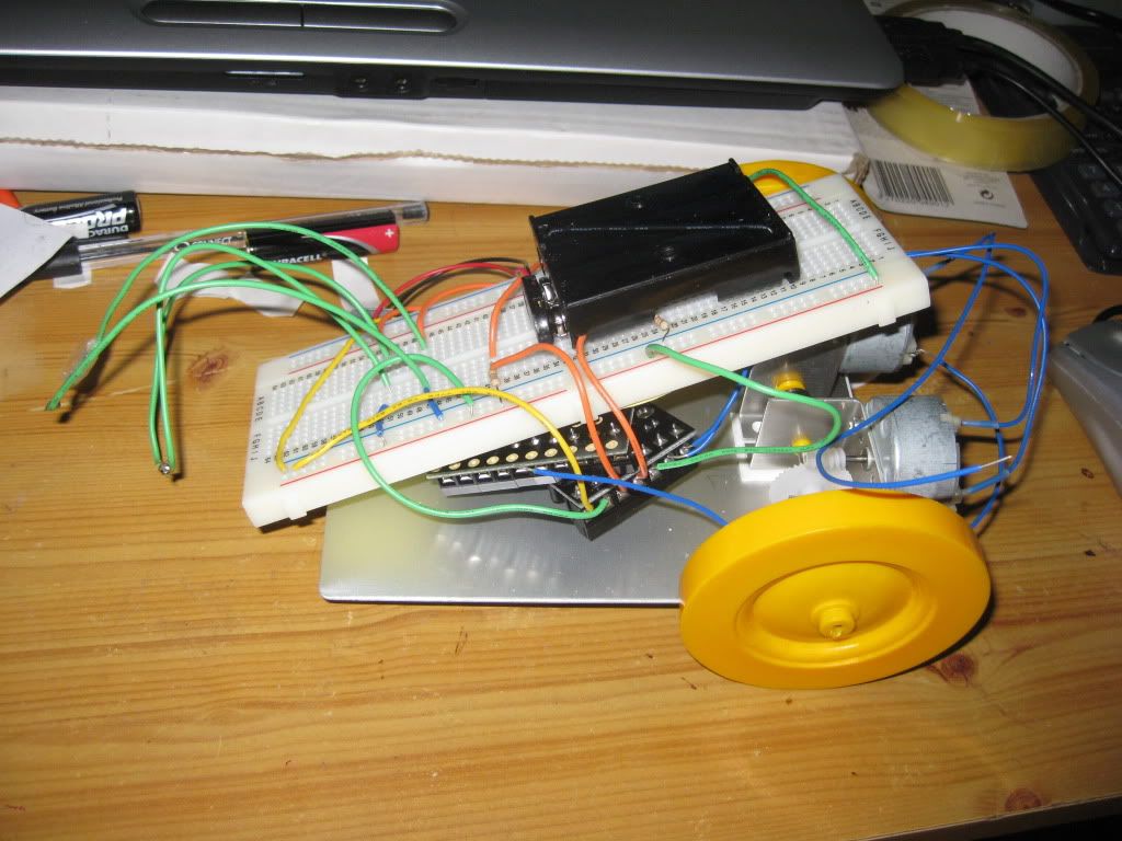
This photo shows how the circuit is placed on the chassis. The breadboard itself creats a cover for the picaxe and motor controller. The reed switches have not yet been perminantly sealed in place on the front of the buggy.
We made the circuit on a breadboard for easy of construction and modification in the event of a mistake being made.
Bellow is the partially constucted circuit. The reed switches are simply plugged into the board as opposed to being on extended wires. This was purely so we could see their position clearly whilst we were still configuring the layout off the breadboard.

The final circuit has both reed switches on elongated wires in order for the sensors to be postioned on the chassis closer to the ground and therefore closer to the magnetic strip.

This photo shows how the circuit is placed on the chassis. The breadboard itself creats a cover for the picaxe and motor controller. The reed switches have not yet been perminantly sealed in place on the front of the buggy.

Saturday, 24 April 2010
Initial Programming
main:
readadc 1, b1
readadc 2, b2
select case b1
case 50 to 100
low 2
high 1
case 0 to 49
high 2
low 1
end select
select case b2
case 50 to 100
low 4
high 3
case 0 to 49
high 4
low 3
end select
debug b1
debug b2
goto main
This program would probably move the buggy to move on the magnetic strip. The idea behind this program is that one motor would switch off itself when the buggy goes off the magnetic strip.
Design

The design of our buggy is very simple. The chassis have two wheels and one brass runner. The two wheels are connected at the back of the chassis and the brass runner is situated at the front in middle. The initial idea was to construct circuit with the chassis as a platform. And this circuit would control the working of the two wheel motors. But after trying this configuration, we found that the whole buggy was becoming unstable.

Subscribe to:
Posts (Atom)